Guide pillar with center flange

Standard: 656X Ø40

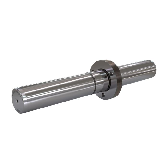
Guide pillar with center flange - for the highest demands and precision

Advantages

    • Higher load capacity and rigidity thanks to the integrated collar
    • Maximum punching precision, as the high-precision coaxially ground collar surfaces ensure precise vertical alignment
    • The low space requirement of the collar enables a compact tool design
    • Easy handling/maintenance
    • The column can be individually adjusted/shortened
    • The higher precision of the structure enables longer tool life
Tool concept

Tool concepts

Previous approach:
The long cylindrical guide pillar is installed either at the bottom or top of the block. As a result, the column bends comparatively strongly when subjected to centrally applied lateral forces, similar to an externally supported and centrally loaded beam. As a result, lateral forces can lead to a comparatively strong lateral deflection of the punching tool. The loss of rigidity increases more and more with column lengths of L>1xd1.
Depending on the desired precision, additional guides must therefore be installed inside the tool. For the designer, this reduces the degree of freedom for positioning the die frame and punch guide/stripper plate.

The Agathon center collar pillar concept:
With the Agathon concept, on the other hand, the integrated center flange fixes the column in the punch guide plate. The column therefore resembles a bending beam fixed on one side by rigid clamping. This results in very efficient stiffening, so that the column deflects far less. This applies to both the upper and lower half of the column. The column length relevant for the deformation calculation also only corresponds to the respective distance from the collar. This design results in a significantly increased rigidity of both halves of the pillar and therefore a very effective increase in the precision of the tool. The result is optimum guidance of the punch/stripper plate relative to the upper and lower parts of the frame. The center collar column is therefore suitable, for example, as a guide for die frames and punch holders.
In addition, tools with center flange guide pillars are very easy to assemble and disassemble, which makes maintenance easier. They can also be designed more compactly due to the elimination of additional guide pillars.

Precision

Stroke accuracy and installation position

Stroke accuracy - repeatability:
The stroke accuracy is in the sub-micrometer range (see image). Agathon guideways are extremely precisely preloaded due to the interaction of the columns, cylinders and rollers manufactured with the highest precision. This is particularly important today, as in modern tool concepts the punch often has to work highly dynamically and with only a minimal cutting gap to the die. Punches that are not guided with sufficient precision lead to uneven punching results and greatly reduced tool life.
Alternatively, the repeat accuracy can of course also be increased by using a higher number of guides. See illustration with examples of two guide pillar frames versus six guide units per tool.

Vertical installation position - concentricity:
The design of the center collar column is such that it is not the cylindrical press-fit part, but the wide supporting collar that determines the 100% right-angled installation position of the column to the guide plate or punch. To ensure high-precision guidance of the punch and die, the coaxiality of the half-columns d1/d2 is also of great importance.

Customized column lengths

Center collar pillars machined to size

The demands placed on stamped parts are constantly increasing, which is why the tool must also meet high standards. In addition, constantly increasing stroke frequencies are forcing the shortest possible strokes, which is why the tools have to be ever more compact. The tighter space conditions make it more difficult to cover the requirements with standardized column lengths alone. In many cases, customized columns are required that are cut to length or precisely manufactured to length. On request, Agathon can manufacture your column in various lengths with tight tolerances. In such cases, L2 and L3 are shortened. This gives the column greater rigidity and the tool correspondingly greater precision.

Installation variants

Installing the guide pillar

Variant 1: Pressing in (see picture)
Prepare the hole, clean carefully and apply oil (no grease). Place the column with f8 in the hole and align with extra-long screws that bridge the distance from the collar to the mounting holes in the plate. Then press in using a hydraulic press or hand press. The pillar has an ISO js4 fit. To ensure the desired press fit, the hole must have an ISO K5 fit.
Caution: Never overpress the pillar once it has reached its installation position. Otherwise it will be deformed.

Variant 2: Shrinking
Heat the component with the hole (e.g. in the oven) and cool the column in the refrigerator. Then carefully insert the column with f8 and allow the temperature of both components to equalize to room temperature once the installation position has been reached. The pillar has fit js4, to ensure a press fit the bore must have N5.

Technical data

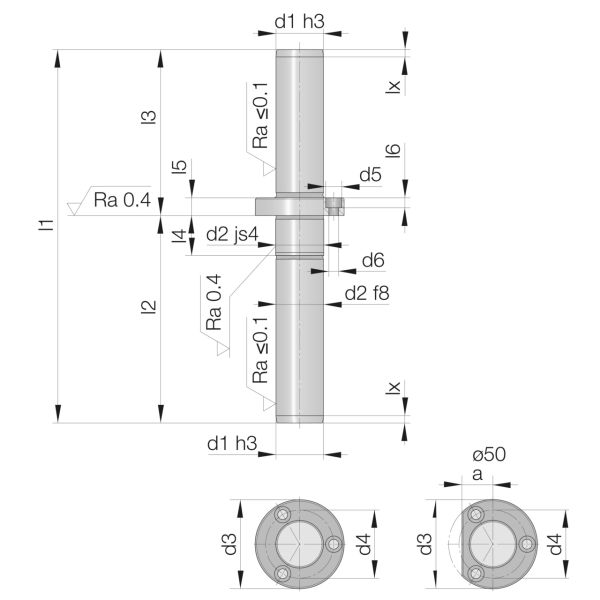
d1  =
Pillar diameter, tolerance h3, precision ground
d2  =
Outer diameter of the guide pillar for fit js4/K5
d3  =
Outer diameter collar
d4  =
Pitch circle Screw holes
d5  =
Diameter Hole for screw head
d6  =
Through-hole for fixing screw
l1  =
Overall length of the guide pillar
l2  =
Length of diameter d1 incl. l4
l3  =
Length of diameter d1 incl. l5
l4  =
Length of the mounting diameter d2
l5  =
Width of the bundle
l6 (mm)  =
Deep hole for screw head
a  =
Federal exemption at Ø50

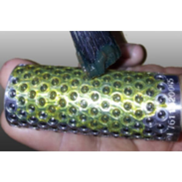
Maintenance and lubrication

Maintenance

● After delivery: Remove rust inhibitor from the centering
● During maintenance:Remove old grease without leaving any residue

Lubrication

● Apply new grease to the cage of the fine centering device

Agathon rolling guides are practically maintenance-free.
The cages are lightly oiled on delivery. They should be washed and lubricated before installation.
Basic lubrication (ball bearing grease with high pressure absorption capacity) before use or during servicing/maintenance increases the service life of the guideway.
Different products can be used depending on the application.
Use without lubricant is generally possible (e.g. applications in clean rooms, the food industry, etc.).
However, the load on the guideway should not be too high. Depending on the load, this will reduce the service life.
In the case of extremely high loads and long periods of use, lubricant can also be added periodically during use. Oil is used to flush away any particles/foreign bodies.

More Information
Application type 1 Lead

Available Dimensions

Grouped product items
Item number: 6560.040.220 STZ Availability d1 (mm) 40 d2 (mm) 42 d3 (mm) 70 d4 (mm) 56 d5 (mm) 11 d6 (mm) 6.6 l1 (mm) 220 l2 (mm) 120 l3 100 l4 (mm) 27 l5 (mm) 12 l6 (mm) 6,8
Item number: 6560.040.240 STZ Availability d1 (mm) 40 d2 (mm) 42 d3 (mm) 70 d4 (mm) 56 d5 (mm) 11 d6 (mm) 6.6 l1 (mm) 240 l2 (mm) 130 l3 110 l4 (mm) 27 l5 (mm) 12 l6 (mm) 6,8
Item number: 6560.040.260 STZ Availability d1 (mm) 40 d2 (mm) 42 d3 (mm) 70 d4 (mm) 56 d5 (mm) 11 d6 (mm) 6.6 l1 (mm) 260 l2 (mm) 140 l3 120 l4 (mm) 27 l5 (mm) 12 l6 (mm) 6,8
Item number: 6560.040.300 STZ Availability d1 (mm) 40 d2 (mm) 42 d3 (mm) 70 d4 (mm) 56 d5 (mm) 11 d6 (mm) 6.6 l1 (mm) 300 l2 (mm) 180 l3 120 l4 (mm) 27 l5 (mm) 12 l6 (mm) 6,8
Item number Availability d1 (mm) d2 (mm) d3 (mm) d4 (mm) d5 (mm) d6 (mm) l1 (mm) l2 (mm) l3 l4 (mm) l5 (mm) l6 (mm)
Log in and create a reqeust

If your desired dimensions are not available in this list, select the most suitable one and note your specifications in the inquiry.