Subscribe to Newsletter
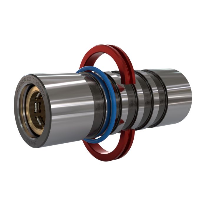
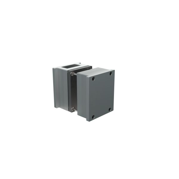
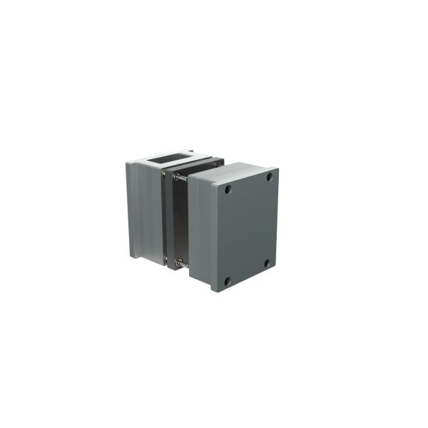
Rolling bush system
Standard: 7231
Rolling bush system for system guide pillars for minimal wear and precise closing of the tool halves without offset
Advantages
- Highest system precision thanks to backlash-free preloaded profile rollers. Five to twelve times longer service life than conventional sliding guides
- Space saving enables higher production with the same tool size
- Easiest handling: low maintenance, durable and no pairing required despite roller guide
- Displaceable retaining ring (standard 8005) enables use across several plate thicknesses
- Can be combined with all guide pillars from the Agathon product range
- Patented product: more info see here https://www.agathon.com/patents
- Contains products containing lead. For further information see: https://www.agathon.com/REACH
Combined guiding and centering
Guiding and centering

Konzepte im Vergleich
Guiding and centering concept
- Combination of two different systems in the mold
- The guide pillars only take over the coarse alignment of the mold during most of the closing movement
- Only on the last millimeters of the closing stroke do the flat centering devices take over the fine alignment
- This can be a problem with long, or sensitive mold areas
- The flat guides are subject to relatively high wear
- The Agathon Guiding System Plus takes over all guiding and centering tasks with just one assembly over almost the entire clamping stroke
- Smooth and highly precise guidance thanks to preloaded profile roller cage
- No jerky sliding during mould movements
- Easy handling: Low maintenance, durable, no pairing required despite roller guide
- Nearly wear-free
Conventional approach
The Agathon concept
Cost benefits

Konzepte im Vergleich
Advantages of the Agathon concept
- Four main guides and four flat centering devices are required
- The production of the pockets for flat centering devices is complex, time-consuming and imprecise
- Two systems in the tool require valuable space
- Precision depends on manufacturing tolerances and wear condition of the guiding and centering elements
- High lubricant and maintenance requirements
- Dirt ingress due to abrasion and particle formation
- Pocket production for flat centering is no longer necessary, which saves time and costs
- Enlarging the working area by up to approx. 30% for additional cavities, slides or tempering
- Thanks to backlash-free preloaded guides with profile rollers, precision remains at the highest level over the entire service life
- Low lubricant and maintenance requirements increase the productivity of the system, reduce maintenance costs and protect the environment
Previous approach
The Agathon concept
Product features
Key features and highlights
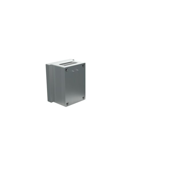
- The roller bushing can be adapted to different plate thicknesses by positioning the retaining ring accordingly
- The ring, which can be reordered as a spare part, can be used with roller bushing system 7231 and system guide pillar 6701
- Safe fixing thanks to heat-resistant O-ring (up to 200 °C)
- Tool is already centered when the preload is reached
- Abrasion on spotting surfaces and plunging cores is prevented
- Tool service life is significantly increased
- Minimum quantity lubrication is sufficient
- Rolling bush with brass profile roller cage allows cleaning in an ultrasonic bath and temperatures up to 170 °C
- Optimal for clean room, high-precision, micro-injection molding and high-temperature applications
- Significantly higher travel speeds and therefore higher production output possible
Retaining ring (standard 8005) enables adaptation to different plate thicknesses:
Long centering travel:
Optimized for high-end applications:
Advantages of the Agathon Guiding System Plus

Flexibility - One for all
Advantages at a glance
- Thanks to this concept, only one size is required in stock. The guide can continue to be used if the tool and plate thicknesses change
- Compatibility: retrofitting to tools is possible without reworking plates
- No pairing required: Any bushing of the appropriate diameter of standard 7231 can be combined with any system guide pillar of standard 6701 of the appropriate diameter from the Agathon product range. Attention: Do not exceed length l2max
- Spare parts available from stock
- The division of tasks between main guide and end centering is eliminated
- Simplification of the tools: Fewer components and less space required on the clamping surface, significantly lower manufacturing and assembly costs
- Thus more cavities and higher productivity on the same clamping surface
- Existing flat centering devices can be removed when retrofitting the Agathon Guiding System Plus
- Backlash-free preloaded guide with profile roller cage ensures maximum precision and part quality over the entire service life of the tool
- The service life is 5-12 times longer compared to conventional systems
- High process reliability avoids rejects and production stops
- Lower maintenance requirements and higher productivity
Flexibility thanks to adaptability to different plate thicknesses using retaining rings:
Better utilization of the clamping surface:
More service life and precision:
Scope of delivery: incl. 1 ring clamp standard 8005 in the respective diameter. Material of bush and rollers: 100Cr6 (1.3505), hardened 62-64 HRC Material of cage: brass CuZn39Pb3 (2.0401) Temperature resistance: up to approx. 170°C
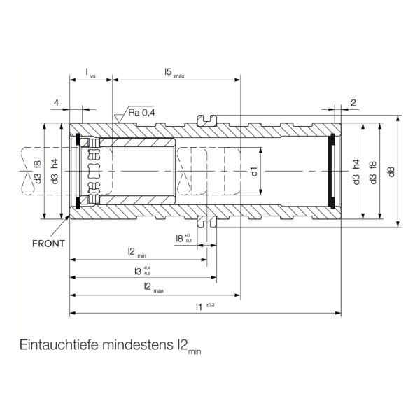
Technical data
d1
=
Corresponding pillar diameter
d3
=
Outer diameter of the guide bush
d8
=
Outer diameter of the retaining ring (flexible collar)
=
Entry into the preload (l2max - l5max)
l1
=
Overall length of the guide bush
l2 min
=
Recommended min. immersion depth using shortest 6701 pillar with thickest bracing plate l6
l2 max
=
Maximum immersion depth when using longer pillars
l3
=
Mounting positions of the retaining ring (flexible collar)
l5 max
=
Maximum possible centering path when using longer pillars
l6 (mm)
=
Lift-off plate (see standard 6701)
l8
=
Width of the retaining ring (flexible collar)
f max
=
Maximum centering offset at the start of centering
Entrance C
=
Basic dynamic load rating in [N] - Initial load capacity
Closed C0 (l2max)
=
static load rating in N at l2max, tool closed
Closed C0 maxP
=
static load rating in N at l2min (using thickest recommended wiper plate l6)
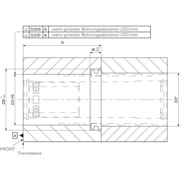
Dimensional drawing Installation tolerances
Accuracy requirements
- The pillar and bushing are installed in bores with tolerance H5
- Alternatively, if less accuracy is required, the tolerance H6 can be used
- Pay attention to the installation direction (FRONT)
- If the largest hole spacing of the main pillar is less than 250 mm, the perpendicularity of the locating hole to the parting line should be <0.005 mm per 100 mm length of the guide pillars.
- If the largest hole spacing of the main pillar is greater than 250 mm the perpendicularity of the mounting hole to the parting plane should be <0.010 mm per 100 mm length of the guide pillars.
- If the largest hole spacing of the main pillar is less than 250 mm the positional accuracy should be <0.01mm (i.e. ±0.005 mm)
- If the largest hole spacing of the main pillar is greater than 250 mm the positioning accuracy should be <0.02mm (i.e. ±0.01 mm)
- Recommendation for best performance: pre-drilled plates with sanding allowance to the desired tolerance or have plates produced with the recommended tolerance
Installation tolerances:
Rectangularity:
Position tolerances:
* = Depending on the required accuracy, the following plates can be be cut to size for easier assembly
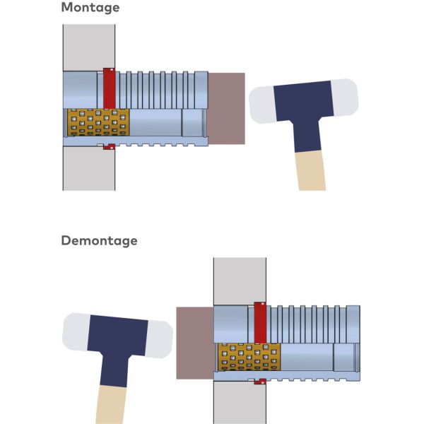
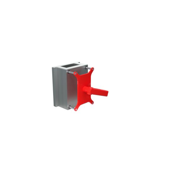
Image installation and removal
Assembly, disassembly and maintenance of the Guiding System Plus
- Clean and remove corrosion protection before assembly, then lubricate
- Position the retaining ring correctly, insert the O-ring
- Tap into the fit with light blows, use a rubber mallet or spacer
- Do not tap the retaining ring or ring clamp
- Use a rubber mallet or spacer
- Do not tap the retaining ring, ring clamp or cage
- Do not pull on the ring clamp
- Regularly rotate the bushing and pillar by 60°
- First remove the old grease completely, then apply new grease
- Minimum quantity lubrication is sufficient
- When replacing the O-ring, observe temperature resistance (FKM)
Assembly:
Dismantling:
Maintenance:
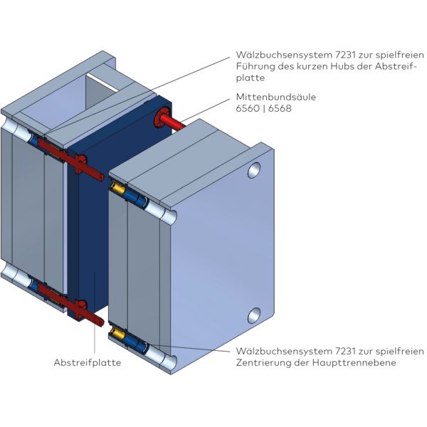
Führung einer Abstreifplatte
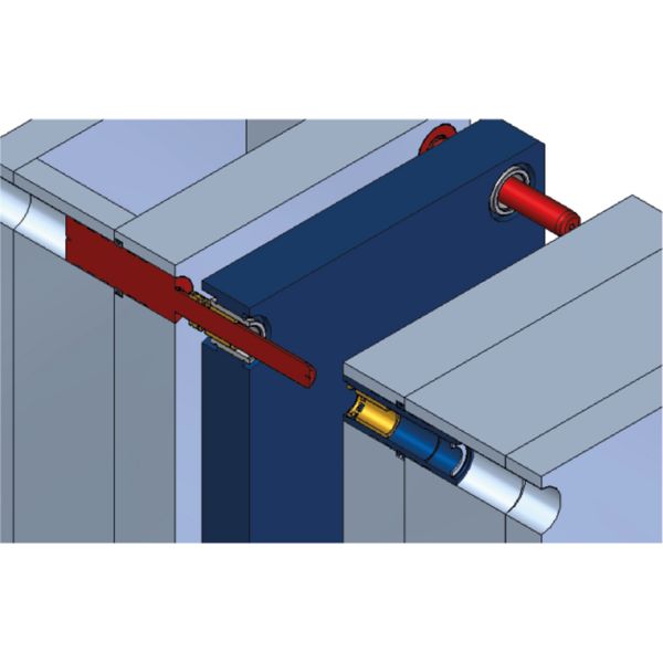
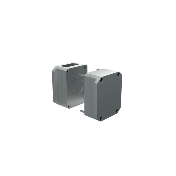
Guidance of a wiper plate on the column
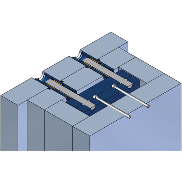
Guidance of ejector plates (short stroke)
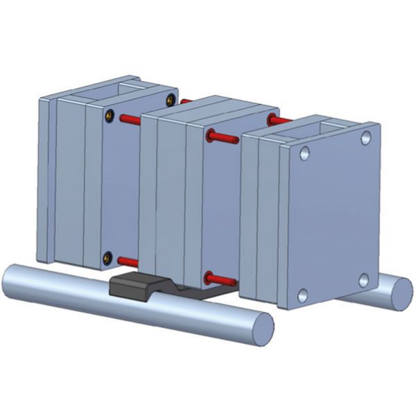
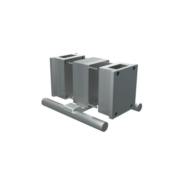
Main guide in the stack mold
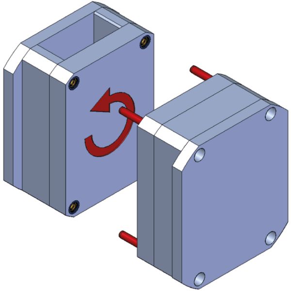
Main guide for turning tools
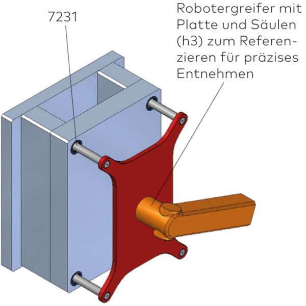
Centering for handling
| Application type 1 | Center, Lead |
|---|